

Autonomous LinkQuad quadcopter with Computer Vision


In 2012, the Computer Vision Group acquired a new quadcopter for their flying family. It is a new model named LinkQuad from the company UAS Technologies Sweden AB. The drone has an autopilot board from the same manufacturer, two slots for WiFi-enabled Gumstix boards running Linux Ångström for higher-level control and a Point Grey camera module with a pan-tilt platform. Quite enough for us to make it a little smarter. If you are here for watching and not for reading, you may go directly to the video.
My job in this project consisted in making the LinkQuad compatible with some control applications already existing in the group. In summary, it meant making the LinkQuad compatible with the group's framework, which is used by the control applications to interact with the drones.
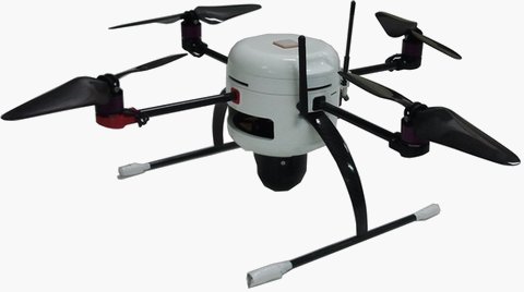
LinkQuad quadcopter. Manufacturer: UAS Technologies Sweden AB.
Existing framework
Since 2011, control software from the group uses a common framework, named MAVwork, to interact with the different drones in the lab. At that moment, I saw the need, proposed the project and coded the first version on an AR.Drone during a three-month stay at the Australian Research Centre for Aerospace Automation (ARCAA). Since then, the framework support for other multirotor models has grown throughout the years. The link below (after all this text, under "Source code") will take you to the project files.
Thanks to MAVwork, applications can interact with the drones through a common API, so they do not need to worry about the hardware specifics or communications. For every drone, there is a customized proxy that deals with everything and makes the drone MAVwork-compliant and controllable from the API. With a down-facing camera, the framework also provides some out-of-the-box automatic flying modes for taking off, landing and hovering. Take-off and landing use to be dangerous stages as the propellers are close to the ground. To make everything safer, applications can tell the framework to perform these operations automatically with its already-tested internal algorithms. In the same way, if things go wrong during the mission, developers can back off to the framework's hover mode. As it is based on vision, there is no need for GPS and it may work either indoors or outdoors. Despite everything is implemented in software, the drones need some basic hardware to perceive the world. This hardware is missing in some models and it must be added.
Hardware modifications
To properly handle the automatic modes, MAVwork needs a camera looking downwards and an accurate and precise altitude measurement. The LinkQuad comes with a barometer, which is fine for high altitude flights, but it does not provide enough quality measures to fly near the ground. This is the reason why we had to add an extra ultrasound sensor. In the picture, you can see our first mounting, with the sensor attached to the propeller bar. However, in the final setup we screwed it to the quad's body under the bar to avoid noise spikes due to vibration.
The camera is embedded in the black rounded module at the bottom. It is the default camera module for the LinkQuad. I just fixed the position of the pan-tilt servos so it is always looking downwards. The ground images are used by MAVwork to estimate the drone's speed and pass it to the control application or stabilize the drone in the MAVwork's internal modes.
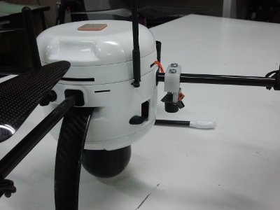
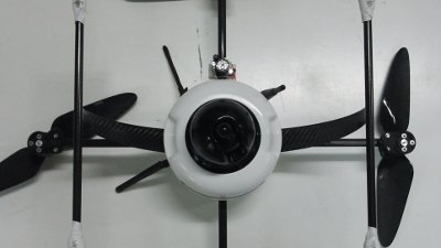
Extra ultrasound altitude sensor and bottom camera looking downwards for speed estimation.
Software development
The LinkQuad support was added to MAVwork by programming a specific proxy. The existing MAVwork proxy for the AscTec Pelican was used as starting point. It had a generic skeleton which could be customized to other drone models by just writing some code snippets to communicate with the autopilot and other sensors.
For the LinkQuad proxy, accessing the autopilot from the Gumstix board was pretty easy. The API is clear and simple and the UAS Tech guys kindly spent a couple of days at our place explaining how everything worked and answering all our questions. They also helped us connecting the ultrasound sensor to one of the autopilot's AD converters and gave me some sample code to read the camera images. With everything on the desk, I wrote some modules to access DC1394 cameras, to communicate with the LinkQuad autopilot and to read the altitude from the ultrasound sensor.
Pains, woes and... solutions!
The most tricky part was making the speed estimation work on the onboard Gumstix. The algorithm detects features on the ground and tracks them in consecutive frames. Using a camera model, the features in the image are projected on a flat ground model and their 3D positions are guessed. All the 3D displacements of the features are then combined into a visual estimate of the drone's speed. Read more about the basic algorithm here. Finally, the low-frequency visual estimate is fused in a complementary filter with the high-frequency estimate based on the accelerometer readings.
The algorithm was originally working on the Pelican's Atom board, which is quite more powerful than the Gumstix (at the cost of draining the battery faster), but it was not able to run above 0.1 Hz on the Gumstix. Obviously, it was not even close to enough for our quad dynamics. First, I got to squeeze some CPU cycles by recompiling OpenCV after adding some specific flags to enable the use of the ARM's NEON instructions. However, the fps counter was still below the poverty line.
The trivial workaround was reducing the image size before processing. Once the 640x480 image was scaled down by a factor of 8, the frame rate figures became decent for the required drone dynamics (~10 fps). Anyway, the 80x60 image was not caching many ground features to track above 1 meter high. So, basically there was no speed estimation beyond that altitude and trying to hover or even taking off could have ended in a total disaster.
I had strong hardware constraints that limited the image size to 80x60 and it was not likely that I could increase the computing power of the platform in a reasonable time and keeping battery life. The solution showed up after discussing with two colleagues. When altitude becomes higher, traits on the ground become smaller from the camera point of view and scaling down has a worst impact on feature detection. However, feature displacements on the image plane due to drone's speed are smaller than at lower altitudes. It means that, for a given speed, a smaller ground area can be scanned to find features that were already present in the previous frame. Therefore, why not picking a smaller floor area at high altitudes? In this way, we keep enough field of view to detect moving features in consecutive frames and, at the same time, as we focus in a smaller piece of the image before scaling down to 80x60, the effective scale down factor is lower and we have better spatial resolution (floor meters per pixel) to detect small features.
The implementation of this idea means clipping a central portion of the image and then scaling it. The scaling factor is directly proportional to a "normalized altitude", while the clipping factor is inversely proportional to it. The product of both factors determines the total processed pixels, which should match the maximum hardware capacity, i.e. 80x60. Clipping is only enabled above an altitude threshold, above which ground features become undetected. The current altitude divided by that threshold is the aforementioned normalized altitude. In our case, the altitude threshold is 1 meter, the base scaling factor (for normalized altitude = 1.0) is 0.125 and the base clipping factor is 1.0. For instance, at 2 meters, a central portion of half the width and half the height of the original image will be clipped and then it will be scaled by a factor of 0.25 to give a total number of 80x60 processable pixels. For every possible altitude above the threshold and clipping/scaling in the allowed range, this number will match the maximum hardware capacity.
Real tests
In the final stage we adjusted the proxy controllers to properly take-off, hover and land. Once it was safe to fly, I programmed a simple speed controller based on PIDs to check the accuracy of the speed estimation. After all, it had been the most sensitive part during development. From a remote console, I commanded sequential speed references trying to follow a rectangle. With the navigation logs, after the flight, the speed estimation was integrated to get a 3D position estimate, which was depicted on the real video. This was done with some camera pose estimation algorithms from my master thesis and manually marking over the image some previously known point positions. The overlaid results do not give an accurate quantitative result, but they are sufficient for having an intuitive idea of the estimation performance.
Of course, like all real sensor integrations, the position estimate accumulates some error over time, which is shown after landing. An important part of this error comes from the few seconds before landing, when the drone is not able to produce a reliable visual estimation, probably due to the lack of ground feature detections at that moment. Despite this, most of the time the speed estimate seems good enough for speed control applications or short-term position estimates over mostly flat floors with some texture.
Ok, enough talking! Here is the video:
Thanks go to Pascual Campoy for the interesting discussion that led to the solution. Special thanks go to Jesús Pestana for his suggestions and his patience as backup pilot during the uncountable hours of field tests.